Links are not yet activated.
To activate, add a link back to submitpr.org from your website and contact @jaycosta on Telegram,
or pay via Solana (from $19.95) for instant activation.
The machine has enough tonnage. The CNC program is correct. The material matches the drawing. Yet, the finished component still does not come out as expected.When that happens, a fabrication team may check the machine, review the program or adjust the operation. But one important factor can be overlooked: the tooling.
Standard punch-and-die combinations are designed for a broad range of conventional bending applications. They perform well when the component geometry, bend radius, flange dimensions and bend sequence remain within their practical working range. Problems begin when a component introduces deeper profiles, closely positioned bends, unusual offsets, restricted clearance or a specific forming requirement.
At that point, the limitation may not be the machine or the program. The tooling geometry itself may simply not match what the component requires.
Why Standard Tooling Falls Short
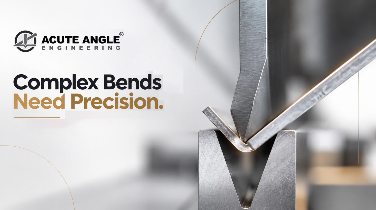
Press brake tooling directly influences how the material moves and deforms during bending. The punch profile, die opening, material thickness, inside radius and available clearance all work together to determine whether the required geometry can be produced consistently.
A straightforward 90-degree bend is usually well within the capability of conventional tooling because the workpiece has sufficient clearance and the required radius falls comfortably within the tooling range. Change the geometry to a narrow flange, deep profile or offset section, and the same tooling may create interference or restrict material movement.
This becomes particularly important when the drawing specifies a certain inside radius. The punch nose and die opening must support that geometry while maintaining the required forming conditions. If they do not, operators may compensate by changing the setup, adjusting the bend sequence or adding secondary operations. While such workarounds may solve an individual component, they become inefficient when the same part enters repeat production.
The result is often more than a tooling issue. Additional tool changes, repositioning and handling can increase setup time and create more opportunities for dimensional variation.
Common Press Brake Bending Problems
Tooling-related problems do not always appear as an obvious collision. They can show up as inconsistent angles, varying inside radii, distorted flanges or difficulty positioning the component for the next bend.
Unusual profiles are one common challenge. If the required contour cannot be produced cleanly with conventional punch-and-die geometry, the tool may need to be shaped around the component.
Deep or restricted-clearance components create another challenge. The formed workpiece needs enough space to move around the punch or die without contacting the tooling. If that space is unavailable, even a correctly programmed operation can become impractical.
Z-bends and offset bends can be difficult because adjacent features may sit close together while moving in different directions during forming. A standard tool may produce the individual bends, but the complete sequence can require unnecessary repositioning or multiple setups.
A specific bend radius can create similar limitations. The required radius must correspond with the punch and die geometry as well as the material characteristics. If the tooling is unsuitable, dimensional variation can occur even when machine settings remain unchanged.
Some operations also require more than simply creating an angle. Hemming, embossing, flattening and controlled forming involve specific material deformation and therefore require tooling capable of controlling that deformation.
Another useful warning sign is excessive setup time. If operators repeatedly change tools, reposition the component or perform secondary operations simply to achieve a geometry that should ideally be produced during bending, the tooling configuration deserves closer attention.
When Special Tooling Makes Sense
Special press brake tooling becomes relevant when the component geometry or forming process cannot be achieved practically with a conventional punch-and-die combination.
The decision does not depend on whether a component looks complicated. It depends on the relationship between the required geometry and what the existing tooling can actually accommodate.
For unusual profiles, specialised tooling can reproduce a required contour instead of forcing the component into a standard geometry. For deep sections and restricted-clearance components, a modified or dedicated profile can provide the working space needed for the formed part to move through the bend sequence.
Specialised tooling can also address Z-bends and offset bends where conventional arrangements create interference or require several setups. Similarly, when a component requires a specific inside radius, dedicated tooling may provide more suitable punch and die geometry for achieving the required profile consistently.
Hemming is another clear example. Since the material must first be folded and then closed, dedicated hemming tooling can provide a more appropriate forming arrangement than a conventional V-die setup.
For applications involving embossing, flattening or controlled deformation, tooling must control the material in a way that a conventional bending configuration may not support. In these cases, the tool geometry is directly connected to the final component shape.
Production volume also matters. An occasional component may justify additional handling and setup time. But when the same sequence is repeated hundreds or thousands of times, reducing tool changes and repositioning can become an important part of process efficiency.
The objective is therefore not to replace standard tooling unnecessarily. It is to identify when standard geometry stops being practical and determine whether a modified or application-specific configuration can solve the actual limitation.
Selecting The Right Press Brake Tooling
Selecting press brake tooling should begin with the component rather than the tool catalogue. The bend angle, material type and thickness, inside radius, flange dimensions, profile depth and complete bend sequence all influence the required configuration.
Clearance deserves particular attention. A tool may successfully form one feature but interfere with another section during the next bend. Reviewing the complete sequence before selecting tooling can reveal these conflicts early and help determine whether a conventional, modified or dedicated configuration is appropriate.
The required forming load must also be considered. Tool geometry needs to remain compatible with the machine’s capacity, while punch and die dimensions must suit the intended application. Material behaviour, tooling dimensions and production conditions should be evaluated together rather than treated as separate decisions.
Production frequency is another practical consideration. For occasional fabrication, a standard configuration may remain suitable even if it requires additional setup. For repeat production, reducing tool changes, simplifying positioning and maintaining consistent forming conditions can have a much greater impact.
This is why press brake tooling is part of the manufacturing process itself. The effective configuration is not simply the tool that fits the machine; it is the one whose geometry, clearance and forming requirements align with the machine, material and component simultaneously.
At AcuteAngleEngg, press brake tooling is developed around application-specific bending requirements where standard configurations may create limitations in geometry, clearance, radius or forming sequence. Whether the challenge involves a deep profile, offset or Z-bend, a specific radius, flange interference or excessive setup requirements, the tooling needs to address the actual manufacturing condition.
Standard tooling creating clearance issues, inconsistent bends or unnecessary setups? Share your component requirements with AcuteAngleEngg and discuss a press brake tooling configuration built around the actual bending application.
Acute Angle Engineering
Shed No. 9, Avadh Ind. Estate, Opp. Panchratna Industrial Estate, Nr. Ramol Bridge, Ramol, Ahmedabad, Gujarat, India
Website: https://www.acuteangleengg.com/