Links are not yet activated.
Is this your press release? Add a link to submitpr.org on your website and verify it — activation is instant and free.
Or upgrade with KIN for permanent activation (from $19.95).
Introduction: Why Engineers Often Confuse DC-DC Converters and Battery Charger ICsDuring power management design reviews, I often see engineers ask the same question:
"Can I use a DC-DC converter instead of a battery charger IC?"
At first glance, this question seems reasonable. Both devices contain switching controllers, MOSFETs, inductors, feedback loops, and protection circuits. Both convert electrical energy from one form to another. In many schematics, they even look similar.
However, from a power semiconductor design perspective, they solve completely different problems.
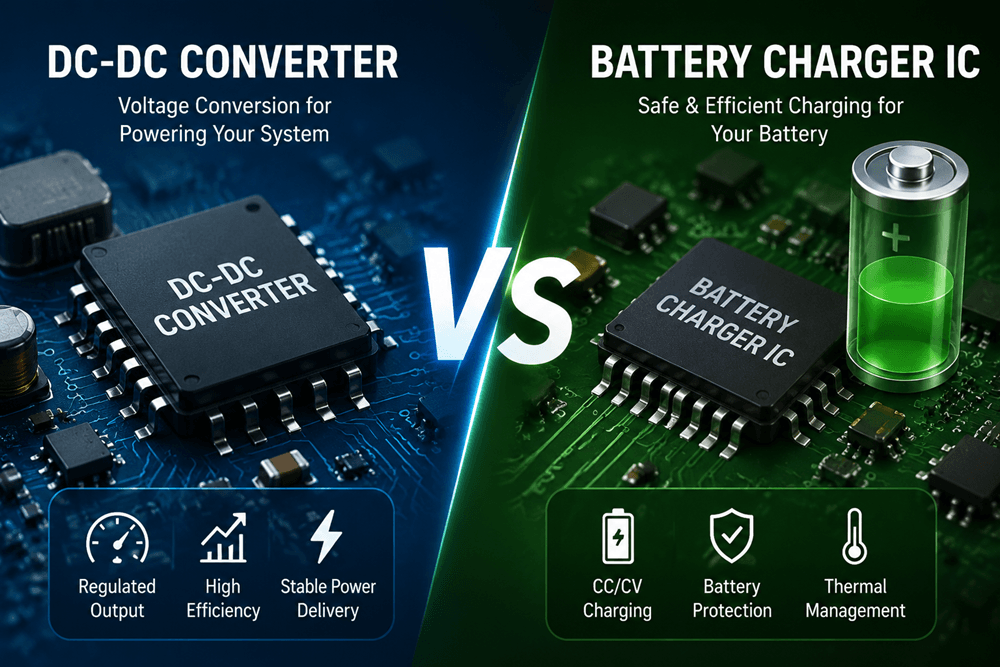
A DC-DC converter is designed to deliver a stable voltage to an electronic load. Its main task is voltage regulation.
A battery charger IC is designed to safely transfer energy into a rechargeable battery. Its task is battery energy management.
This difference becomes critical in portable electronics, IoT devices, industrial equipment, medical instruments, and automotive systems where battery reliability and safety directly affect product performance.
A common design mistake is treating a battery as just another load. A battery is not a resistor or an IC power rail. It is a chemical energy storage device with voltage, current, temperature, and lifetime limitations.
Therefore, selecting between a DC-DC converter and a battery charger IC is not simply a component selection decision. It is a system architecture decision.
1. What Does a DC-DC Converter Do?
A DC-DC converter(https://www.avaq.com/category/power/dc-dc-converters) converts one DC voltage level into another regulated DC voltage.
For example:
12V input → 5V output
5V input → 3.3V output
3.7V battery → 1.8V processor supply
The primary objective is simple:
Provide a stable output voltage regardless of input voltage variation or load changes.
In a typical embedded system, many components cannot directly operate from the battery voltage.
For example:
A single-cell lithium-ion battery has a voltage range approximately from 3.0V to 4.2V.
However:
MCU core may require 1.2V
Digital logic may require 3.3V
USB interface may require 5V
RF circuits may require low-noise regulated rails
A DC-DC converter creates these required voltage rails efficiently.
2. How Does a DC-DC Converter Work?
A switching DC-DC converter usually contains:
Power MOSFET switches
Inductor
Output capacitor
PWM controller
Voltage feedback loop
The controller continuously monitors the output voltage and adjusts the switching duty cycle.
For example:
If the output voltage drops because the load increases:
Feedback voltage decreases.
Controller increases MOSFET conduction time.
More energy is transferred through the inductor.
Output voltage returns to the target value.
This is a closed-loop voltage regulation system.
The converter does not understand:
Battery state of charge
Battery chemistry
Charging cycle
Remaining capacity
Cell temperature
It only knows:
"Is my output voltage correct?"
3. Common DC-DC Converter Topologies
3.1 Buck Converter
A buck converter reduces voltage.
Example:
12V → 5V
Common applications:
Industrial controllers
Automotive electronics
Embedded systems
FPGA and processor power supplies
3.2 Boost Converter
A boost converter increases voltage.
Example:
3.7V battery → 5V USB output
Applications:
Portable devices
LED drivers
Battery-powered sensors
3.3 Buck-Boost Converter
A buck-boost converter can increase or decrease voltage.
This is useful when battery voltage changes during discharge.
Example:
Li-ion battery:
Fully charged: 4.2V
Nominal: 3.7V
Low battery: 3.0V
A 3.3V system rail may require both buck and boost operation.
4. What Is a Battery Charger IC?
A battery charger IC has a completely different purpose.
Its job is:
Safely charge a rechargeable battery according to its chemistry and charging requirements.
Unlike a DC-DC converter, a charger IC must understand battery behavior.
A lithium-ion battery cannot simply be connected to a voltage source.
The charging process requires controlled:
Current
Voltage
Temperature
Charging time
Termination conditions
Modern charger ICs typically implement CC/CV charging algorithms and include protection features such as over-voltage protection, thermal regulation, and input current limiting.
5. Understanding Lithium-Ion Battery Charging
Most portable electronics use lithium-ion or lithium-polymer batteries.
The charging process normally includes several stages.
Stage 1: Pre-Charge
When a battery is deeply discharged, the charger applies a small current.
Purpose:
Protect battery chemistry
Avoid excessive stress on the cell
Stage 2: Constant Current (CC)
The charger provides a controlled charging current.
Example:
A 2000mAh battery may be charged at:
1A
2A
depending on battery specifications.
During this stage:
Charging current remains constant.
Battery voltage gradually increases.
Stage 3: Constant Voltage (CV)
When the battery reaches its maximum voltage:
Example:
4.2V for many Li-ion cells
The charger maintains voltage while reducing charging current.
Stage 4: Charge Termination
When charging current decreases below a defined threshold:
The charger stops charging or enters standby mode.
This prevents:
Overcharging
Excessive heat
Battery degradation
6. The Key Difference Between DC-DC Converter and Battery Charger IC
The simplest way to understand the difference:
DC-DC Converter:
"I need to provide a stable voltage to my circuit."
Battery Charger IC:
"I need to safely store energy inside a battery."
Feature DC-DC Converter Battery Charger IC
Main purpose Voltage conversion Battery charging
Control target Output voltage Battery charging profile
Load type Electronic circuits Rechargeable battery
Charging algorithm No Yes
CC/CV support Usually no Yes
Battery protection Limited Integrated
Temperature monitoring Usually no Common
Typical position Battery → System Adapter → Battery
7. Can a DC-DC Converter Charge a Battery?
This is one of the most common design questions.
The short answer:
Normally, no.
A basic DC-DC converter can regulate voltage and sometimes current, but it does not include battery charging intelligence.
Potential problems include:
Overcharging
The converter may continue applying voltage after the battery is full.
Thermal Stress
Incorrect charging conditions can generate excessive heat.
Reduced Battery Lifetime
Improper charging accelerates battery aging.
For lithium-ion batteries especially, a dedicated charger IC is recommended because charging requires controlled CC/CV operation and protection functions.
8. Why Many Designs Use Both Charger IC and DC-DC Converter
In many real products, engineers do not choose one or the other.
They use both.
A typical architecture:
USB / Adapter Input
|
|
Battery Charger IC
|
|
Rechargeable Battery
|
|
DC-DC Converter
|
|
MCU / Processor / Sensors
The charger IC manages:
Battery charging
Battery protection
Power-path control
The DC-DC converter manages:
System voltage rails
Load regulation
Power efficiency
This architecture is common in:
Smartphones
Wearables
IoT devices
Industrial handheld products
Many modern PMIC solutions integrate charger and converter functions together to reduce PCB size and simplify power management.
9. When Should You Choose a DC-DC Converter?
Choose a DC-DC converter when your main requirement is voltage conversion.
Typical cases:
Battery-powered MCU system
Example:
Battery:
3.7V
Need:
3.3V MCU supply
Solution:
Buck converter
Processor power supply
Example:
12V input
Need:
1.0V CPU core voltage
Solution:
High-current buck converter
Multiple power rails
Example:
Industrial controller:
5V sensor rail
3.3V MCU rail
1.8V communication rail
Solution:
Multiple DC-DC converters
10. When Should You Choose a Battery Charger IC?
Choose a battery charger IC when your product contains a rechargeable battery.
Typical applications:
IoT Devices
Requirements:
Low standby current
Battery lifetime optimization
Wearable Electronics
Requirements:
Small PCB size
Safe charging
Low heat generation
Medical Equipment
Requirements:
Reliability
Battery protection
Long operating time
Portable Industrial Equipment
Requirements:
High charging current
Robust protection
11. Important Design Considerations When Selecting the IC
From my experience designing and reviewing power systems, engineers should evaluate more than voltage and current ratings.
11.1 Battery Chemistry
Different batteries require different charging methods.
Examples:
Li-ion
Li-polymer
LiFePO4
NiMH
Never select a charger IC without checking chemistry compatibility.
11.2 Charging Current
Consider:
Battery capacity
Charging time requirement
Thermal limits
Higher charging current does not always mean better design.
11.3 Efficiency
For battery-powered products:
Every percentage of efficiency matters.
Evaluate:
Switching losses
MOSFET resistance
Inductor loss
Standby current
11.4 Thermal Performance
Power dissipation affects:
Battery temperature
Product reliability
Charging speed
Thermal management should be considered early in PCB design.
12. Common Design Mistakes
Mistake 1:
Using a DC-DC converter as a battery charger.
Mistake 2:
Ignoring battery temperature monitoring.
Mistake 3:
Selecting an IC only based on output voltage.
Mistake 4:
Ignoring standby current.
Mistake 5:
Forgetting PCB layout impact.
Switching power circuits require careful layout:
Short current loops
Proper grounding
Correct capacitor placement
Controlled EMI
Conclusion: Choose Based on the System Requirement
A DC-DC converter and a battery charger IC are not competing components.
They solve different engineering problems.
A DC-DC converter provides efficient voltage conversion for electronic circuits.
A battery charger IC safely manages energy storage inside rechargeable batteries.
For many modern battery-powered products, the best design uses both:
Battery Charger IC + DC-DC Converter + Power Management Logic
Understanding this difference helps engineers create products with better efficiency, longer battery life, improved reliability, and safer operation.
In power management design, the correct question is not:
"Which IC is better?"
The correct question is:
"What function does my system actually need?"
-- End --
About the author -- Avaq Semiconductor
Avaq is a global electronic components distributor that helps businesses source semiconductors, integrated circuits (ICs), sensors, connectors, and other electronic parts. Founded in Hong Kong in 2013, the company connects customers with a large network of qualified suppliers worldwide. Avaq focuses on reliable sourcing, quality inspection, and supply chain risk reduction to ensure authentic components and timely delivery. With customers in over 80 countries, Avaq supports engineers, manufacturers, and procurement teams by making component sourcing faster, easier, and more dependable.
Official web: https://www.avaq.com/